
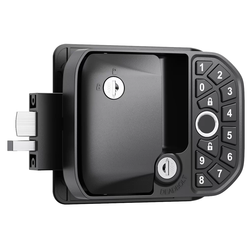
RV Keyless Entry Door Lock ML100-6001
219,99 € Excl. VAT
Multiple Unlocking Methods | Dual Locking Mechanism | Ergonomic Handle Design | Independent Power Supply & Long Battery Life | Excellent Resistance to Harsh Environments | Convenient Hands-Free Access | Direct Replacement Without Modification | Quick and Easy Installation
1. General Specifications
Model : ML100-6001 Electronic Lock
Rated Voltage : DC 6 V
Operating Voltage : DC 3.8–7.2 V
Operating Current: 200 mA (Peak Current ≤ 500 mA)
Standby Current: ≤ 20 µA (Bluetooth Disabled) / ≤ 200 µA (Bluetooth Enabled)
IP Protection Rating: IP65 (Protective Cover Required)
Salt Spray Resistance:
Outside of Door Panel: 96 Hours Neutral Salt Spray Test
Inside of Door Panel: 48 Hours Neutral Salt Spray Test
Coating: 96 Hours Neutral Salt Spray Resistance
Unlocking Methods: Mechanical Key, Fingerprint, Remote Key Fob, Password
Flammability Rating: UL94 V-0
Lock Cylinder Type : Mechanical Lock Cylinder (2,000 Key Combinations)
Drive Mechanism: Electric Motor
Vibration Test:
Frequency: 50 Hz; Amplitude: 5 mm; X, Y and Z Axes; 30 Minutes per Axis; No Abnormalities After Testing (Packaged)
Mechanical Strength:
Outer Flip Cover: Load Capacity 400 N
Inner Flip Cover: Load Capacity 400 N
Service Life / Warranty: 2-Year Warranty from Date of Manufacture or 20,000 Operating Cycles (Excluding Batteries)
Environmental Compliance: RoHS 2.0
Applicable Door Thickness: 35–45 mm
Key Operating Torque: 2.5 N·m
Door Offset Height: N/A
Lock Weight: 1.4 kg
2. Remote Key Fob Specifications
Flammability Rating : UL94 V-0
Remote Control Range: ≤ 15 m
Service Life / Warranty: 2-Year Warranty from Date of Manufacture or 7,000 Operating Cycles
3. Component Specifications
Housing: Aluminum Alloy,Black High Salt-Spray-Resistant Coating;
Front Flip Cover:Zinc Alloy,Black High Salt-Spray-Resistant Coating;
Pressure Plate:Zinc Alloy,Black High Salt-Spray-Resistant Coating;
Locking Bolt:Zinc Alloy,Trivalent Chromate Conversion Coating,Color Zinc,72 h;
4. Communication
Bluetooth Communication:Remote Key Fob Communication
5. Environmental Conditions
Operating Temperature: −40°C to +70°C
Operating Humidity:≤ 80% RH
Storage Temperature:−40°C to +70°C
Storage Humidity:≤ 90% RH
Operating Altitude:−60 m to 4,000 m
4.1 Mechanical Key Unlocking
Insert the mechanical key into the “DEADBOLT” keyhole and turn it 90° clockwise.
Turn the key 90° counterclockwise and remove it. Then insert the same key into the “HANDLE” keyhole and turn it 90° clockwise.
Note: The mechanical key can be inserted into either keyhole first. There is no required sequence.
4.2 Mechanical Key Locking
Insert the mechanical key into the “DEADBOLT” keyhole and turn it 90° counterclockwise.
Insert the mechanical key into the “HANDLE” keyhole and turn it 90° counterclockwise.
Note: To remove the key from the “DEADBOLT” keyhole, it must be turned an additional 90° counterclockwise.
The “HANDLE” keyhole can remain in either the locked or unlocked position as required. This does not affect the actual locking of the lock, provided that the “DEADBOLT” is securely locked.
4.3 Password Unlocking
Ensure that the lock is in the locked position.
Enter the password (default password: 1234) and press the “UNLOCK” button within 3 seconds. If more than 3 seconds have elapsed, the password must be entered again. The motor retracts the latch into the lock body, and the buzzer emits three beeps.
Insert the mechanical key into the “HANDLE” keyhole and turn it 90° clockwise.
4.4 Password Locking
Ensure that the lock is in the unlocked position.
There are two locking methods:
- Method 1: Press and hold the “LOCK” button for 3 seconds. The latch bolt will extend.
- Method 2: Enter the password and press the “LOCK” button to lock.
After successful locking, the buzzer emits two beeps.
Insert the mechanical key into the “HANDLE” keyhole, turn it 90° counterclockwise, and remove the key to lock the external handle.
4.5 Changing the Password
First, make sure you know the current password (or the default password).
Press and hold the “8” and “LOCK” buttons simultaneously, then release both buttons. Within 5 seconds after the buzzer sounds, enter the old/default password (1234) and press the “LOCK” button.
Enter the new password and press “LOCK”. Enter the new password again and press “LOCK” to confirm.
When the new password has been successfully set, the buzzer emits three long beeps and the keypad backlight turns off.
Example: Changing the default password from 1234 to 5678
The default password is 1234.
Press and hold “8” and “LOCK” simultaneously, then release both buttons. Enter “1234” and press “LOCK”.
Enter “5678” and press “LOCK”. Enter “5678” again and press “LOCK”.
Unlock using the new password: enter “5678” and press “UNLOCK” to initiate unlocking.
4.6 Remote Key Fob Pairing
On the back of the lock, move the remote control switch to the “ON” position. Press any button on the front keypad to wake up the lock. Once the keypad backlight turns off, the remote key fob function is enabled.
Lock side: Press and hold the “FOB Learn” button for 3 seconds. The lock buzzer emits one long beep, and the keypad backlight starts flashing, indicating that the lock has entered pairing mode.
Remote key fob side: Once the lock is in pairing mode, press and hold either button on the remote key fob. The red indicator on the remote key fob remains illuminated, indicating that pairing has started.
When the lock buzzer emits one long beep and the keypad backlight turns off, pairing is complete. The remote key fob can now be used to lock and unlock the device.
Notes:
- To pair another remote key fob, repeat Steps 1–2.
- To disable the remote key fob function, move the switch to the “OFF” position.
- One lock can be paired with up to three remote key fobs.
4.7 Remote Key Fob Unlocking
Move the remote control switch on the lock to the “ON” position.
Press the unlock button on the remote key fob. The red indicator on the remote key fob flashes slowly. When the lock receives the unlocking signal, the keypad backlight flashes and the buzzer emits three beeps. The motor retracts the latch into the lock body, allowing the external handle to be released and pulled.
Insert the mechanical key into the “HANDLE” keyhole and turn it 90° clockwise.
4.8 Remote Key Fob Locking
Move the remote control switch on the lock to the “ON” position.
Press the “LOCK” button on the paired remote key fob. The red indicator on the remote key fob flashes slowly. When the lock receives the signal, the keypad backlight flashes and the buzzer emits two beeps. The motor extends the latch bolt.
Insert the mechanical key into the “HANDLE” keyhole and turn it 90° counterclockwise.
4.9 Fingerprint Unlocking
Ensure that the lock is in the locked position.
Place a registered finger on the fingerprint sensor. The green indicator on the fingerprint module remains illuminated, and the buzzer emits one long beep.
Press the “UNLOCK” button to confirm unlocking.
The latch bolt retracts into the lock body, and the buzzer emits three beeps.
Insert the mechanical key into the “HANDLE” keyhole and turn it 90° clockwise.
4.10 Fingerprint Locking
Ensure that the lock is in the unlocked position.
Place a registered finger on the fingerprint sensor. The green indicator on the fingerprint module remains illuminated, and the buzzer emits one long beep.
Press the “LOCK” button to confirm locking.
The latch bolt extends, and the buzzer emits two beeps.
Insert the mechanical key into the “HANDLE” keyhole and turn it 90° counterclockwise.
4.11 Fingerprint Registration
Press and hold the “0” and “LOCK” buttons simultaneously, then release both buttons. The buzzer emits two long beeps, and the keypad flashes for 2 seconds.
Enter the cabinet lock password and press the “LOCK” button. The buzzer emits one short beep, and the blue indicator on the fingerprint module illuminates, indicating that the lock has entered fingerprint registration mode.
Place a finger on the fingerprint sensor. When registration is successful, the green indicator illuminates and the buzzer emits one long beep. Then lift your finger.
Recreational Vehicle (RV) Entry Doors
Motorhome Entrance Doors
Caravan and Travel Trailer Entry Doors
Camper Conversion Entry Doors (subject to installation compatibility)
Packaging Specifications
Each lock is individually packaged with an EPE foam insert and an inner box.
Each package includes one pen-type screwdriver, four alkaline zinc-manganese batteries, one user manual, and one YS915 electronic key.
Precautions
1. Do not operate the product beyond the limits specified in this specification.
2. If any changes to the specifications in this document are required, please submit the relevant requirements in advance.
3. In the event of any discrepancies between this document and other technical documents or information, this document shall take precedence.
4. Do not use the product in environments containing flammable gases or other hazardous conditions.
5.Operators must wear protective gloves during transportation and installation to prevent injuries caused by falling objects or other hazards.
6. Do not strike or impact the lock during installation, as this may damage its components. Do not clean or wipe the lock with chemical reagents, as they may damage the surface coating.
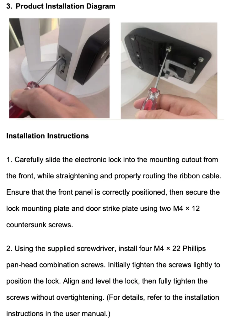
7.Ensure that the door panel remains level during installation. The mounting cutout in the cabinet door must match the required dimensions of the lock body.
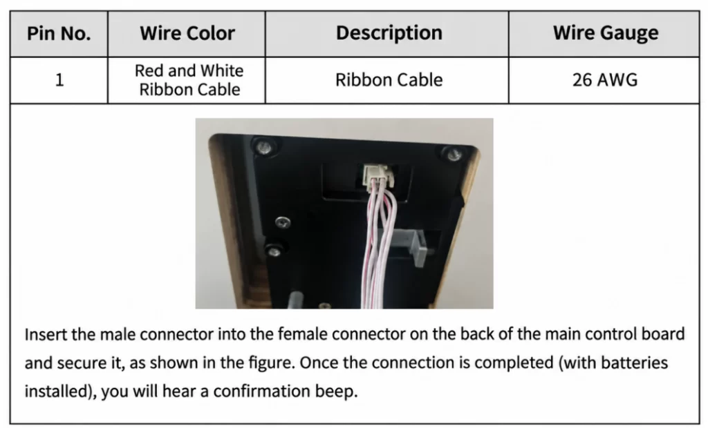
8. After installation, connect the wiring harness. Do not wrap the connecting cable around the lock or pull it forcefully, as this may damage the lock connector and cause the lock to malfunction.
Product Specification
1. Product Appearance
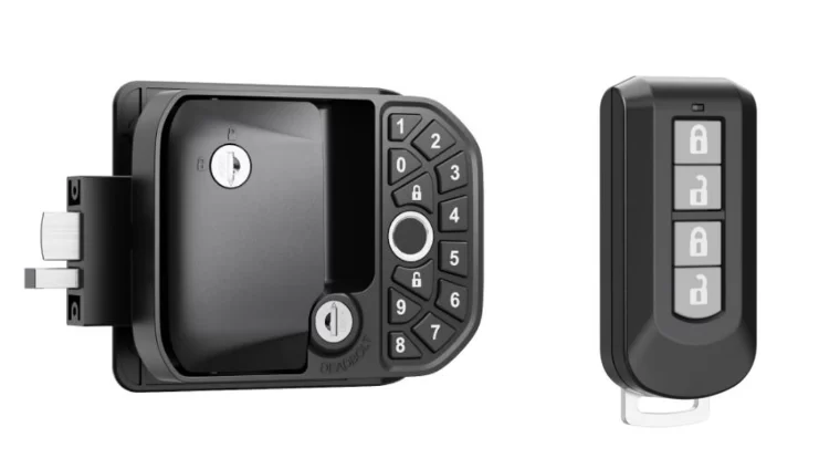
1.1 Product illustrations of the electronic lock and a remote-control key
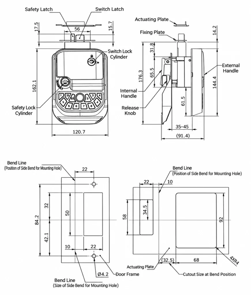
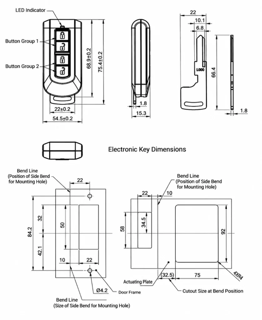
1.2 Overall dimensions and mounting cutout
lock
key
4.Wiring Diagram
No downloads are currently available for this product.
This FAQ document is designed to assist engineering procurement, R&D teams, and sales representatives in quickly understanding the product classification, selection criteria, material specifications, and customization options for Mineon industrial locks and latches.
A: Mineon specializes in locking and latching solutions engineered for industrial enclosures, specialty vehicles, electronic cabinets, and heavy machinery. Our primary categories include:
- Cam Lock / Cam Latch: Includes $1/4$-turn (Quarter-Turn) locks, hygienic locks, and T-handle locks. Compact structure and easy installation, suitable for standard electrical enclosures and control cabinets.
- Compression Latch: Includes mini, adjustable, and Lift-and-Turn compression latches. Applies continuous pressure to sealing gaskets upon latching, delivering exceptional waterproof, dustproof, and anti-vibration performance.
- Handle Lock / Handle Latch: Includes swinghandle locks and T/L-handle locks, offering comfortable operation and high security, commonly used in large control cabinets and distribution boxes.
- Paddle Latch (Flush Mount): Features a flush-mounted design, including stainless steel paddle latches and hood latches, ideal for construction machinery, RVs, camper vans, utility trailers, and marine hatches.
- Multi-point Latch: Operates via rod systems to lock top, bottom, or multiple points simultaneously, ideal for tall cabinet doors requiring uniform sealing and security.
•6.Smart Lock / Smart Latch: Supports electronic, RFID card, or remote signal access, designed for energy storage cabinets, telecom base stations, and automated industrial equipment.
A: They differ significantly in operating principle and application scenario:
- Cam Lock: The cam/latch rotates purely on a flat plane when turning the key or drive insert. Suitable for compact spaces, general cabinets without heavy gasket compression requirements, and high-frequency opening.
- Compression Latch: The latch first rotates into position and then travels axially to pull the door tightly against the frame (typically providing a $4text{mm}–6text{mm}$ compression stroke).
••Selection Advice: If the cabinet requires an ingress protection rating (such as IP65/IP66), utilizes foamed sealing gaskets, or operates in high-vibration environments (e.g., vehicles, rail transit, heavy equipment), a Compression Latch must be specified to prevent vibration loosening and ensure tight seal integrity.
A: Outdoor and mobile equipment face constant vibration, mud, water, and extreme temperature fluctuations. Recommended choices include:
- Stainless Steel Paddle Latches (e.g., ML100-3003 series): Flush mount design saves external space, while SUS304/316 construction provides superior corrosion resistance.
•2.Lift-and-Turn Compression Latches (e.g., ML100-2012 series): Featuring T-handles easily operated even with gloves, high clamping force, and strong anti-vibration performance.
A:
- Zinc Alloy (Die-Cast Zinc): The most widely used material, available with Chrome Plating or Black Powder/E-Coated finishes, offering an excellent balance of cost-effectiveness and mechanical strength.
- Stainless Steel (SUS304 / SUS316): Ideal for food and pharmaceutical processing equipment (hygienic design), outdoor marine environments, and highly corrosive chemical applications.
••Engineering Plastics / Polyamide (Nylon): Lightweight, electrically insulated, and corrosion-resistant, commonly used in light-duty enclosures.
A: Multiple locking and access configurations are offered to suit varying security and operational requirements:
- Keyed Alike (KA): All locks open with the same key, convenient for centralized maintenance and fleet management.
- Keyed Differently (KD): Each lock has a unique key for elevated security levels.
••Tool / Insert Drive (Non-Keyed): Options include Triangle, Double-Bit, Square drive inserts, or Wing Knobs / T-Handles, suited for industrial power cabinets requiring fast maintenance access without strict key management.
A: We provide a comprehensive suite of accessories to complete your installation:
- Cams / Latching Arms in various shapes and offsets;
- Rod Systems and Rod Guides for multi-point latching;
••Dust Covers, Keys, Mounting Brackets, Gaskets, and Fastening Nuts.
To request technical datasheets, 3D CAD models, sample orders, or bulk pricing, please reach out to the Mineon team:
- Website: mineon.de
- Email: info@mineon.de / Jane.zou@mineon.de
••Address: Stormstraße 3, 41469 Neuss, Germany